Show designers usually avoid splitting chains across racks if the chained shells are straight up, but if shells are fanned out at angles then they may choose to spread the chained shells across multiple racks that are tilted at the required angles, usually one shell per rack (“Cross-loading”). Alternatively, designers sometimes use racks or rack assemblies that are pre-built with tubes angled to match the angles of the chained shells (“fan-racks”). When you layout your racks in Finale 3D, you sometimes need to add constraints in the addressing procedure to direct the software to put chains in the racks you intend for them, when multiple alternatives exist.
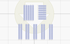
Figure 1 – Rack layout with three possibilities for racking chains of fanned shells
For example, Figure 1 shows a rack layout with various possibilities for racking a show consisting of seven chains of 5 shells each (-20, -10, 0, 10, and 20 degree angles). The group of five vertically oriented racks in the top left are fanned out at the matching angles, so each chain of five shells could be cross-loaded with one shell in each of those racks. The group of seven horizontally oriented racks in the top right are fan-racks, each with five tubes at the matching angles (there is no way to tell the angles of the individual tubes from looking at the rack layout diagram, though you would know what types of racks they were if you added the racks and arranged the layout yourself). The seven chains could all be loaded into these fan-racks, one chain per rack. The third possibility is the pairs of racks at the base of the diagram. Since the pairs of racks aren’t close together, this option is probably undesirable or even physically impossible, but a rack layout for a show containing independent shells in addition to chains in the same position may have racks like these, and it may be necessary to direct the software not to load chains into them.
All three of these possibilities presume the show designer wants each chain to have fanned out shells instead of firing five chains simultaneously, one angle per chain. By the time you address the show, you’ve already made this decision, because the chains in the script either contain shells at fanned out angles or at one angle per chain.
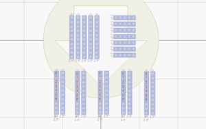
Figure 2 – The bad possibility–chains assigned to unintended racks, far apart
Figure 2 illustrated the bad possibility, in which each chain’s shells are spread across racks that are far apart. The numbers in the racks (0-6) are the pin numbers firing the seven chains. All the shells of a chain are ignited by the same pin, so as you can see, the five shells of the chain fired by pin 0 occupy the top-left tube of each pair of racks. This racking assignment might be the result of addressing the show with the addressing settings shown in Figure 3.
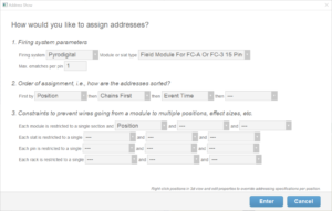
Figure 3 – No rack related constraints, so chains may end up in any racks with matching angles
The Finale 3D addressing algorithm will assign racks to shells roughly in the order the racks were inserted into the rack layout, subject to their compatibility, so you could avoid Figure 3 by cutting the pairs of racks out (control-x) and pasting them back (control-v) to make the software consider them last. There’s a better solution though — to use constraints to filter out the possibilities that you don’t want. Let us imagine that you would like to cross-load the chains into the racks in the upper left. What’s the difference between those racks and the pairs of racks at the bottom? The racks in the upper left are all close together, in the same “rack cluster” (i.e., snapped together in the rack layout view). To restrict chains to the same rack cluster, ensuring the shells are close together, you can simply add the constraint, “pin constrained to a single rack cluster”. The reason that constraint applies to chains is that all the shells of a chain are ignited fuses that trace back to the same pin on the firing system module, so constraining shells of the same pin to a single rack cluster will necessarily constrain shells of the same chain to a single rack cluster.
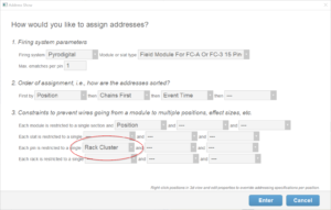
Figure 4 – Constraining a pin to a single rack cluster constrains chains to a single rack cluster.
The addressing settings of Figure 4 add the rack cluster constraint to the pin. The result is shown in Figure 5.
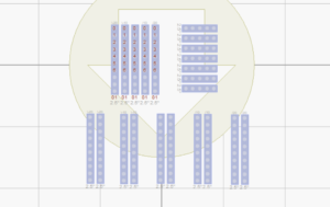
Figure 5 – The pairs of racks at the bottom do not satisfy the rack cluster constraint for the chains.
If you would prefer to use the fan-racks in the upper right, each chain being housed in a single rack, the constraint is simply “pin constrained to a single rack”, i.e., just as in Figure 4 except “Rack” instead of “Rack Cluster.”
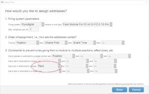
Figure 6 – The rack constraint forces each chain to go into a single rack.
The result of the rack constraint is that the chains go into the fan racks, since those are the only racks in the layout that satisfy the constraint that each chain’s shells (all on the same pin) go into the same rack.
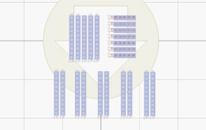
Figure 7 – The fan-racks each have tubes at -20, -10, 0, 10, 20 matching the of the chain’s shells.
If you notice, the addressing settings in Figures 3, 4, and 6 all sort chains first, after positions. This sorting option doesn’t matter in this example show consists only of chains, but for shows that have positions with chains and individual shells, it is often a good idea to address the chains first so they fill up the racks first, and individual shells fill in the leftover tubes. If you have fan racks in the rack layout intended especially for chains, you need the sort order to prevent the individual shells from filling them up.