If chain lengths don’t match the length of racks, cross-loading the chains across racks may be the way to go. Just look at Figure 1. The techniques for cross-loading fanned chains are described in Cross-loading chains with angled shells or using fan-racks, but those techniques don’t always work for straight-up chains. A fanned chain doesn’t have the option of loading into a single straight rack because of its angles, so it naturally loads across racks that are tilted at the matching angles. A straight-up chain can load into a single straight rack or across racks. You need to add an addressing constraint if you want it to load across racks.
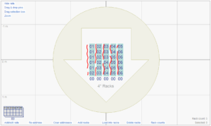
Figure 1 – Bad result: if chain lengths don’t match the rack length, straight-loading will cause chains to split across racks.
Adding the addressing constraint “Tube Index — Chain” to the pins does the trick. The addressing constraints in the addressing dialog, shown in Figure 2, enable you to restrict every module “to a single XXX” for any term XXX you choose; or to restrict every slat “to a single XXX” for a term XXX; or to restrict every pin, or every rack, similarly. The most common addressing constraint is to add the term XXX = “Position” to the module constraints, which restricts every module to the same launch position to avoid long wires travelling from the module to multiple positions. You can see the “Position” constraint in Figure 2, although this constraint is not specifically related to chain loading.
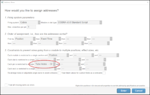
Figure 2 – Adding “Tube Index — Chain” to the pin constraints forces every shell of the chain to have the same tube index in its rack.
The addressing constraint to make chains cross-load is a constraint on the pin, as circled in Figure 2, which restricts every pin “to a single Tube Index — Chain.” What makes this constraint work is that all the shells of a chain are ignited by the same e-match, and therefore by the same pin. Thus any restriction on the pin will necessarily apply to all the shells of a chain ignited by the pin. The “tube index” is just the order of the tubes in the rack, so if every shell of a chain is restricted to the same tube index, then the chain shells will line up in a straight row across a series of racks, as shown in Figure 3.
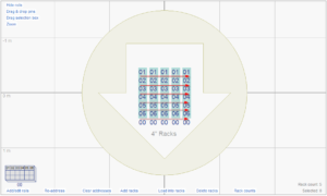
Figure 3 – Good result: if every shell of a chain has the same tube index, the chain loads in a row across the racks — cross-loading!
The constraint “Tube Index — Chain” includes the phrase “– Chain” to indicate that the constraint only applies to chains. It does not apply to flights of independent shells ignited by the same pin. This subtle distinction is a convenience that allows you to add the constraint for addressing in general without it affecting pairs of shells or flights.
The constraint also has one other nuance that isn’t explicit in its name. The “Tube Index — Chain” constraint implicitly adds a “Chain Reference” constraint to the pin, which restricts the pin to a single chain (or non-chained shells), preventing multiple chains from being e-matched to the same pin. If multiple chains were e-matched to the same pin, then the “Tube Index — Chain” constraint would force all their shells to be at the same tube index, which would make for a very long row of racks.
Lastly, the “Tube Index — Chain” constraint only applies to pins. Adding the constraint to the modules or slats does nothing because it doesn’t make any sense.