Racks and positions orientations are represented in Euler Angles as heading (a rotation about the global Y-axis), pitch (a rotation about the global X-axis), and roll (a rotation about the global Z-axis). Finale 3D chooses this representation for racks because the three angles correspond directly to the three degrees of freedom of rotations for mortars in a traditional wooden rack. The three angles also happen to correspond to the most common rotations of positions (side to side, forward/back, and compass heading), so they serve as a natural representation for both racks and positions.
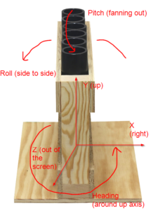
Figure 1 – To remember the meaning of heading, pitch, and roll, imagine a rack of mortars in this orientation.
To cement the meanings of heading, pitch, and roll in your mind, please imagine the wooden rack as shown in Figure 1. The mortars of the rack in this orientation have three degrees of freedom for rotation corresponding to heading, pitch, and roll:
- Roll is the side to side rotation/tilt of the entire rack.
- Pitch is the fan-out angle of the tubes within the rack.
- Heading is the direction the rack is facing.
Heading, pitch, and roll
The orientation of a rack or position may be calculated by a sequence of three rotations, rotating first by pitch about the global X-axis, then by roll about the global Z-axis, and finally by heading about the global Y-axis. All angles are “right-handed” rotations, meaning that that if you aimed the thumb of your right hand in the direction of the axis of rotation, then your fingers would curl in the positive direction of the angle. Following this convention, heading is a counter-clockwise rotation, viewed from above; pitch aims the up vector forwards toward the viewer (i.e., aiming out of the screen) when viewed from the front; roll aims the up vector to the left on the screen when viewed from the front.
Table 1 – Order of Euler Angle rotations producing a rotated vector v’ from vector v
| v’ = v * R1 * R2 * R3 | Rotation |
|---|---|
| First rotation (R1) | Rotate around global X-axis by pitch |
| Second rotation (R2) | Rotate around global Z-axis by roll |
| Third rotation (R3) | Rotate around global Y-axis by heading |
The order of the three rotations matters to their definition. If roll were to apply before pitch, then <heading = 0°, pitch = 90°, roll = 90°> would represent a mortar aiming to the left because the 90° roll around the global Z-axis would tilt the mortar fully to the left, and then the subsequent pitch around the global X-axis would spin the mortar around its own axis without changing the direction it is pointing. By contrast, since pitch actually applies first, <heading = 0°, pitch = 90°, roll = 90°> represents a mortar aiming straight out of the screen at the viewer because the 90° pitch rotation around the global X-axis rotates the mortar fully forward out of the screen, and the subsequent roll around the global Z-axis spins the mortar around its own axis without changing the direction.
Referring back to the picture of the rack in Figure 1, the order of rotations of Table 1 is the only possible choice that matches the physical constraints of the rack. If heading were the first rotation, for example, then pitching around the global X-axis wouldn’t fan the mortars within the rack because the rack wouldn’t necessarily be facing the X-axis as it is in Figure 1.
Table 2 – Range of angles in conversions from orientations
| Angle | Range |
|---|---|
| Heading | (-180°, +180°] |
| Pitch | (-180°, +180°] |
| Roll | [-90°, +90°] |
Any orientation can be represented by heading, pitch, and roll angles in the ranges of Table 2. Some orientations have multiple representations within these ranges that happen to be equivalent. The orientation represented by <heading = 0°, pitch = 90°, roll = 90°> is the same as the orientation represented by <heading = 90°, pitch = 0°, roll = 90°> for example. Mathematically, in this Euler Angle representation all rotation sequences with a roll of +/- 90° are equivalent to other rotation sequences in which +/- heading and pitch sum to a constant value. In circumstances in which an orientation is converted to a rotation sequence that is not uniquely defined, Finale 3D will choose the rotation sequence with pitch = 0°, which creates a 1-to-1 relationship between orientations and Euler Angles in the ranges of Table 2. These ranges are not limits, though, in Finale 3D‘s user interface and tables. You can enter any heading, pitch, and roll value into the position and model table columns, including numbers outside these ranges.
Origin man
The coordinates of positions are relative to the model they are attached to, if they are attached to a model, and are global coordinates otherwise. To symbolize the global coordinate system and to convey the correct sense of scale, a six foot tall human facing the forward camera is drawn at the coordinates <0, 0, 0>. His name is “Origin Man.”
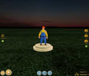
Figure 2 – “Origin Man” stands at coordinates <0, 0, 0>.
In the global frame of reference, the X-axis aims to the right of the screen, the Y-axis aims up into the sky, and the Z-axis aims out of the screen toward the viewer (you).
Rotating positions
To rotate the heading of a position, right click the position and select “Rotate (heading)”. A rotation wheel will appear. If you drag the reddish arrow around the wheel, you will adjust the heading of the position. The heading of the position is the global heading, analogous to a compass heading, which is unaffected by the pitch or roll of the position. The arrow on the top of the position disk always aims in the same direction as its heading.
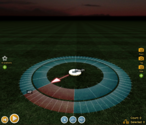
Figure 3 – Adjust the heading by right-clicking the position and selecting “Rotate (heading)”.
The pitch of the position aims the arrow on the position disk down into the ground (positive pitch) or up into the sky (negative pitch), as shown in Figure 4.
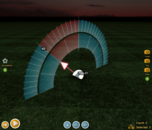
Figure 4 – Adjust the pitch by right-clicking the position and selecting “Rotate (pitch)”.
The roll angle rotates the position on its side. Following the right-hand rule, a positive roll rotates the position to the left when viewed from the front, since the Z-axis aims toward the front.
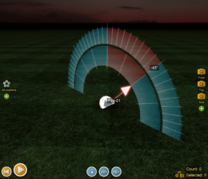
Figure 5 – Adjust the pitch by right-clicking the position and selecting “Rotate (roll)”.
Rotating positions on a wall
The heading, pitch and roll angles are convenient for representing orientations that are resting on the ground or are pitched or rolled by less than 90 degrees. They aren’t at all convenient for representing sideways positions, such as positions mounted on a wall or side of a tower facing outward. The position shown in Figure 6 can be rotated with the right-click context menu command, “Rotate (around position’s up vector)”. The other rotation commands shown in Figure 3, Figure 4, and Figure 5, are useless for rotating positions on walls.
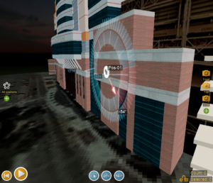
Figure 6 – Use “Rotate (around position’s up vector)” to rotate positions on walls. The other rotation commands are useless.
Moving positions on a wall
Positions will automatically orient themselves flatly against the surface when you are dragging them onto a wall, but you may need to adjust the coordinates. The right-click menu item “Move on axis…” brings up three colored axes in the frame of reference of the position. You can drag the red, green, and blue arrows to move the position along any of its local axes, as shown in Figure 7.
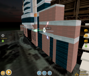
Figure 7 – The right-click menu command “Move on axis” bring up three arrows that you can drag to adjust the position.
Arranging positions on towers and trusses
The right-click menu commands to rotate and move positions apply to all selected positions, as a group, centered around the position you are right-clicking. For towers and walls, you may find it easier to arrange positions in a pattern on the ground, and then rotate the entire pattern up sideways and project it onto the tower or wall. Consider two examples.
Example 1: Arranging positions vertically with even spacing on the side of a tower that tapers toward the top. The rulers and tools for arranging positions work best on the ground, so arrange the positions on the ground in a line in regular intervals. Then select all the positions in the line, right-click on the first position in the line, and do “Rotate (pitch)” or “Rotate (roll)” to rotate the entire line up into air. Then do the menu item “Positions > Coordinates > Project positions on their down axis to nearest surface” to project the positions against the tower surface behind them.
Example 2: Arranging positions on the seats of a ferris wheel. Measure the diameter of the ferris wheel by right clicking on one of the seats and doing “Measure to this point” from the context menu. Knowing now the diameter of the circle, insert N positions into the scene with the menu item, “Positions > Insert > Insert multiple…” and then do the menu item “Positions > Arrange into pattern > Into a circle…” to arrange the positions into a circle of the right diameter — on the ground. Slide the circle of positions on the ground so it is in front of the ferris wheel, as if the ferris wheel were casting a shadow on the ground in front of it and the positions were on the shadows of the seats. Right click on the position farthest from the ferris wheel base, and do “Rotate (pitch)” to pitch the entire circle of positions upward. Then right click one of the positions and do “Move on axis…” to move the circle of positions up and back to register against the ferris wheel model.
Exporting coordinates and angles
The Finale Generic CSV export format (see Finale Generic CSV (full show export format)) contains the world coordinates and angles of the positions and effects of an exported show in its Coordinates column. The exported CSV converts the coordinates and angles to world coordinates, as a convenience. By contrast, the table windows in Finale 3D contain relative coordinates and angles, i.e., effects are relative to their positions; and positions are relative to the models they are attached to if they are attached to models. Figure 8 shows an example of the table windows involved in calculating the world coordinates and angles of effects.
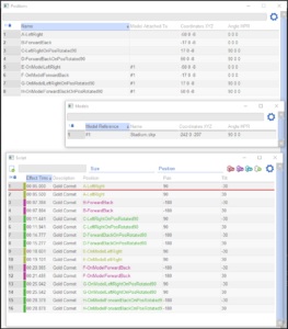
Figure 8 – In the table windows, effects are relative to positions, which are in turn relative to the models they are attached to.
The example CSV export that you can download from Table 3 below corresponds to Figure 8. It covers all the major scenarios — left/right angles, forward/back angles, effects in rotated positions, and effects in rotated positions attached to rotated models. The test file has eight positions, each with two effects. The first position has effects at 30 degrees left and 30 degrees right relative to the position. The second position has effects at 30 degrees forward and 30 degrees back. The next two positions are the same as the previous two except the positions are themselves rotated 90 degrees clockwise. The next four positions are the same as the previous four except that the positions are attached to a model that is itself translated and rotated 90 degrees clockwise.
Table 3 – Example files and downloads
| Download link | Explanation |
| angle-test.csv | Test file for exporting angles and coordinates |