If a shoot site will be used over and over again for repeated events, such as in a theme park, the shoot site may be pre-configured with a fixed number of stationary mortars at pre-defined angles and with pre-defined firing system wiring. Take a look at Figure 1, below.

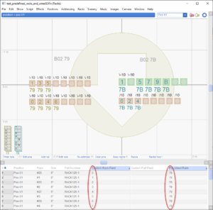
Figure 1 – Launch position with 32 tubes at pre-defined angles and with pre-defined module and pin numbers.
The rack layout of Figure 1 represents a launch position labeled B02 with two Pyrodigital modules, 79 and 7B. The tubes in this launch position are modelled in Finale 3D as individual single-tube racks. There are 32 tubes at this launch position, and thus there are 32 racks, represented by the peach and green squares. The peach squares are 5″ tubes and the green squares are 6″ tubes. Additionally, all 16 of the 5″ tubes on the left side are tilted 10 degrees to the left. Only two of the 6″ racks on the right side are tilted to the left (the rest are straight up). All of the 5″ tubes on the right are tilted 10 degrees to the right.
Further to the specifications of this launch position, the 16 tubes on the left are all constrained to module 79, and to pin numbers counting from 0 to F beginning with 0 in the lower left, then 1 above it, then 2 on the bottom row again, then 3 above it, etc.; the 16 tubes on the right are all constrained to module 7B and to pins in a similar order beginning with 0 in the lower left. Not all of the tubes are filled in this example, which is why some of the tubes do not have pin numbers in them, but you can observe that all of the tubes that do have pin numbers are laid out consistently with these specifications.
Imagine that the specifications illustrated by Figure 1 are pre-defined by the shoot site. Then any show design that is compatible with this shoot site must have effects that fit in these specific tube sizes at these specific angles — and the firing system addresses of the effects must match the pre-defined modules and pins of the tubes that the effects go into.
This section shows how to set up your shoot site in Finale 3D such that the addressing functions will assign firing system addresses in keeping with these complex specifications of the shoot site.
Setting up the shoot site in Finale 3D
The addressing functions in Finale 3D like “Addressing > Address show” assign firing system module and pin numbers to the effects, and additionally rack and tube numbers if you’ve added racks to the launch positions. To set up the shoot site for pre-wired tubes as shown in Figure 1, you need to,
- Create definitions of the racks, specifying the size and “Pre-wired pins” option.
- Add all 32 racks to the rack layout and tilt them to the correct angles using the blue control point in the lower right.
- Specify the “Pre-Assigned Rails” for the launch position (79 and 7B in this example).
- Specify the module and pin numbers for all 32 racks exactly as you want them to be laid out.
Step 1: Creating the rack definitions
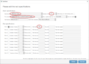
Creating the rack definitions may be the simplest step of all. The shoot site of Figure 1 requires only two rack definitions, a 5″ and a 6″ rack. Both racks have a single tube. Both racks are mortar racks with the “Pre-wired pins” option of “Specified by Custom Rack Field”. Figure 2 shows the dialog for creating one of these racks:

Figure 2 – Definition of a single-tube rack for a pre-wired shoot site.
Step 2: Adding the racks to the launch position
Once you’ve created the two rack definitions, you can add all 32 rack instances to the launch position by clicking on the rows representing the racks in the effects window while viewing the launch position in the rack layout window. It is easiest to do this by hand, one at a time. For each one that needs to be angled, you can click on the blue dash control point in the lower right corner of the rack and drag it to tilt the rack to the correct angle. After completing this step, your launch position should have peach and green squares looking like Figure 1, although no pin numbers or module numbers yet.
Step 3: Specify the “Pre-Assigned Rails”
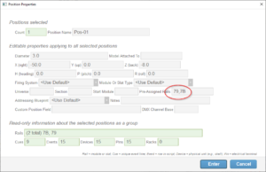
Knowing that your launch position is to use modules 79 and 7B, edit the position properties for the launch position and type in “79,7B” into the “Pre-Assigned Rails” field. The terms “Rail” and “Module” mean the same thing unless the firing system partitions its module pins into slats (Rails). Since the Pyrodigital firing system does not do that, the terms “Rail” and “Module” are synonymous.
Setting the Pre-Assigned Rails for the position allocates those specific modules to the position. You can edit position properties by right clicking a position in the 3D view, or by clicking the “Edit rails” link at the bottom of the rack layout view, or by opening the positions window and editing the Pre-Assigned Rails column. Editing the numbers in the positions window is the quickest user interface if you are configuring multiple launch positions.

Figure 3 – Pre-allocating specific rails (modules) for the launch position.
Step 4: Specify the module and pin numbers for the racks
Refer again to Figure 1 and look at the numbers circled in red. The table in this diagram has a lot of the columns hidden in order to make the columns important to this example more visible (hint: to hide columns, right-click on the column header and select “Hide column” from the context menu; or click on the blue gear menu in the upper right). The two red circles show the “Custom Rack Field” and the “Pre-Wired Rails” for the racks in the launch position. These fields are editable. You can click on a rack in the rack layout view to select it in the table, and then you can edit these two field values for that rack.
If you recall in Step 1, you defined the racks with the “Pre-wired pins” option of “Specified by Custom Rack Field”. That option enables you to specify different pins for each rack instance in the position. Since these racks have just a single tube each, each rack needs only a single number, representing the pin number pre-wired to its one and only tube (if the rack had multiple tubes you can specify a comma-separate list of pin numbers instead of a single number). So, for this example, just fill in the desired pin number for the tube in the “Custom Rack Field” of the rack representing the tube.
The “Pre-Wired Rail” field sets a constraint that the rack is only compatible with a list of one or more specified rails. In this example, each rack has one tube so it obviously involves only one module. Simply type the appropriate module number into the “Pre-Wired Rail” field of each rack.
What next?
Steps 1-4 complete the setup of the shoot site for pre-wired tubes. After completing these steps, you can design a show and assign firing system addresses with “Addressing > Address show” or any of the other addressing options. Finale 3D will assign firing system addresses consistent with the specifications you’ve laid out. Looking back again at Figure 1, notice that some of the pin numbers in the counting sequence appear to be missing. The second green square, for example, which would be expected to house pin 3, is empty. Why is that? The show design for this example has only one 6″ shell aiming to the left 10 degrees. Thus that tube cannot be used for anything. Since the tube cannot be used for anything, neither can the pin that is pre-wired to it. Pin 3 of module 7B must be unused for this show design.
While designing a show you can check at any time if your design fits in the constraints of your shoot site by clicking “Addressing > Address show” and seeing if there are any errors. If your show design uses angles or sizes that you don’t have in the shoot site, you’ll find out about it with errors in the summary dialog from the addressing function.