Ladder racks like the Evolved rack shown in Figure 1 have rows spaced apart like rungs of a ladder to allow each row to be configured with its own independent angle. This rack structure contrasts with Fan angle racks that have independently rotatable tubes.
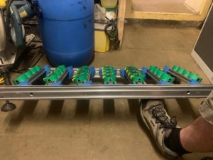
Figure 1 – The rows of the ladder rack, like rungs of a ladder, are spaced apart. Each row can have an independent angle.
If your firing system modules or slats are connected to the ladder rack with “pre-wired pins,” then the angles of the ladder rows will affect the viability of pin addresses, setting up a rather complex set of constraints for assigning firing system addresses. Finale 3D‘s addressing functions can satisfy all the constraints if you set up your racks and addressing configurations properly. Setting up the configurations requires some careful choices, but once you have the configurations set up you will find that addressing the show is blissful. The addressing functions take care of all the work for you.
The two configurations you’ll need set up are,
- The addressing blueprint (or equivalently the fields in the “Addressing > Address show” dialog)
- The rack definition in the “Create rack” dialog
This section walks through the configuration choices twice, using the PyroSure firing system to show the configuration choices for a firing system with slats, and the FireOne firing system to show the configuration choices for a firing system without slats.
Pre-configured vs. adjustable tilt rows
If you specify the row angles of the rack before addressing the show and choose “Single-shot rack, fixed tube angles” for the rack structure in the “Create rack” dialog, then the rack is said to be “pre-configured”. The addressing functions like “Addressing > Address show…” will fill the rows with effects whose angles match the angles of the rows. Figure 2 shows the “Create rack” dialog. To set the row angles for a rack, fill in the “Row tilt” fields for the eight rows with tilt angles in degrees, following the angle convention that -90 is to the left, 90 is to the right, and 0 is up.
If you leave the row angles unspecified and instead choose the “Single-shot rack, tilt adjustable row angles” for the rack structure, then the addressing function will define the row angles on the fly as it assigns firing system addresses to the shots. Whenever you use the“Single-shot rack, tilt adjustable row angles” option, it is advisable to assign firing system addresses sorted by angle or tilt within each position, as shown in paragraph 2 of Figure 3, for two reasons: First, it guarantees that the rows are fanned out outwards without crossing angles; second, it guarantees that the addressing algorithm doesn’t put shots of the same angle in multiple rows if they could be in the same row, which could result in inefficient filling of the rack.
In addition to the addressing sort order, the tube loading order option in the rack definition can affect the angles of the rows for adjustable tilt row racks, so for this kind of rack please follow both these guidelines:
- Set the tube loading order in the rack definition to “By rows, left to right” (which is also the default).
- When addressing, sort the addressing order by tilt or angle as the primary condition after Position.
The reason for these guidelines is that the first effect assigned in each row will set the angle of the row. The “By rows” loading order means the effects being addressed will fill out the first row, to the extent their angles are compatible, before moving on to the next. The “Across rows” loading order means the effects being addressed will fill out the first tubes in each row before moving on to the second tubes, and so on. The best approach to guarantee the rows are filled completely is to “fill” all the left-most rows first, and work your way to the right as the rows fill up, which requires (1) and (2). Imagine if you have 25 shots to fill a 5-row rack, and your shots are in 5 angles, 5 shots each. If you sort by angle but your tube loading order is “Across rows” instead of “By rows”, then the first five shots would be assigned to the first tube in each of the five rows, forcing ALL of the rows to be the first angle. Those first five shots would get racked and the next 20 would not fit in the rack because all the rows are aiming a single direction!
These guidelines are not required for pre-configured tilt row racks, only for adjustable tilt row racks. The guidelines still apply if you use the Re-arrange tubes in adjustable angle racks to avoid collisions option when addressing.
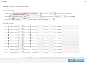
Figure 2 – The ladder rack configuration for PyroSure requires the “Sequential for each row” option, since each row is bound to a firing system slat.
Pre-wired pins
The PyroSure firing system uses slats that are wired individually to Evolved ladder rack rows. Since all the tubes in a row have the same angle, all the effects addressed to the same slat must therefore be the same angle. The addressing blueprint shown in Figure 3 adds the constraint in paragraph 3 that slats are restricted to a single angle. If you are addressing for ladder racks with Pyrosure, you need this constraint for the ladder racks.
Your show probably has other kinds of racks in it as well, though, and you may want to use other constraints and sorting criteria for other racks in the show. The “Addressing > Address show” function applies a single set of addressing criteria for the entire show, so if you need different criteria for different parts of the show you need to use either 1) the “Addressing > Fill down addresses” function, or 2) addressing blueprints. Addressing blueprints are rule sets or templates of the addressing criteria that look approximately the same as the “Addressing > Address show” dialog. You can assign different addressing blueprints to different positions of the show, and then use the “Addressing > Address show using blueprints assigned to positions” instead of the “Addressing > Address show” function. To use a different addressing blueprint for your ladder racks, you need to split off your ladder racks and their effects into their own positions, and then assign your custom addressing blueprint to those positions.
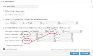
Figure 3 – The addressing blueprint (or equivalent “Addressing > Address show” dialog) for PyroSure requires that each slat is restricted to a single angle.
For most firing systems, you will want to allocate a single module to the ladder rack. In paragraph 3 of Figure 3, the two circled constraints connected by a red line restrict each module to a single rack, and each rack to a single module. The combination of those two constraints creates a 1:1 relationship between modules and racks. This is the right configuration for ladder racks or any other kind of rack that you want to bind to a single module per rack.
The PyroSure slats are pre-wired to the tubes in the ladder rack in a pre-defined (and obvious) order, beginning with pin 1 at the top and pin 4 at the bottom for each row, since each row is pre-wired to a slat with four pins. The “Sequential for each row” option shown in Figure 2 is the choice that will guarantee that pin layout. There are other options that are applicable to other firing systems, but the “Sequential for each row” option is the correct choice for PyroSure because PyroSure uses a separate slat for each row. The various pre-wired pin options are all illustrated in Pre-wired pin options. The illustration of “Sequential for each row” is shown here in Figure 4.
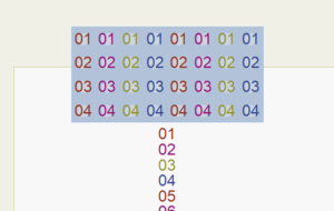
Figure 4 – The “Sequential for each row” option works for firing systems like PyroSure that assign a separate module or slat to each row.
PyroSure example
The rack definition and addressing blueprint of Figure 2 and Figure 3 are the correct setup for the PyroSure firing system. To illustrate the end result, consider an example of a single fan of five effects at different angles. In a ladder rack, the shots of the fan will need to fill into separate rows since each row has just one angle. The rows are pre-wired to slats, and therefore the fan of five effects will consume pin 1 of slats A, B, C, D, and E, as shown in Figure 5.
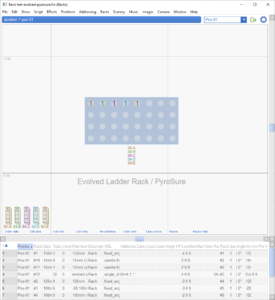
Figure 5 – A ladder rack fan of five angles requires five rows. For PyroSure, the top five tubes correspond to pin 1 of slats A, B, C, D, and E.
FireOne configuration
The setup for FireOne is slightly different from PyroSure because FireOne doesn’t use slats for its addressing scheme. Figure 6 illustrates the natural pin pattern for pre-wiring a FireOne module to a ladder rack (see Pre-wired pin options for other options).
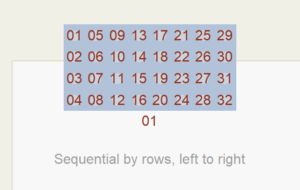
Figure 6 – The “Sequential by rows, left to right” option works for firing systems like FireOne that use a single module and pin range for the entire rack.
You can select this “Sequential by rows, left to right” pre-wired pins option in the “Create rack” dialog, as shown in Figure 7.
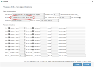
Figure 7 – The ladder rack configuration for FireOne can use the “Sequential by rows, left to right” option.
The FireOne system doesn’t use slats in its addressing scheme, so the addressing blueprint for ladder racks using FireOne doesn’t specify anything in the slats line of paragraph 3 of the addressing blueprint shown in Figure 8.
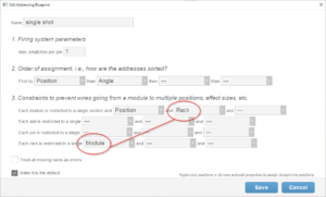
Figure 8 – The addressing blueprint for FireOne doesn’t have constraints for slats, because there aren’t any.
FireOne example
The rack definition and addressing blueprint of Figure 7 and Figure 8 are the correct setup for the FireOne firing system. As with the earlier PyroSure example, consider a single fan of five effects at different angles. In the ladder rack, the shots of the fan will need to fill into separate rows since each row has just one angle. The tubes are pre-wired to the full range of the module pins, but the filled tubes are not consecutive in that range. Filling the top five tubes is obviously correct, but less obvious is that the pin numbers of those tubes won’t be consecutive pins. Look at Figure 9 and then refer back to Figure 6 to see that the allocated pins correspond to the pre-wired constraints.
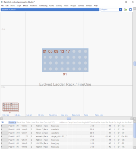
Figure 7 – A ladder rack fan of five angles requires five rows. For FireOne configured with “Sequential by rows, left to right”, the top five tubes are pins 1, 5, 9, 13, and 17.
