When you define a rack with the “Create rack” function you have the option specifying a “Pre-wired pins” constraint, which pre-defines the one and only pin number that can go into each tube holder of the rack. This feature is required if your racks physically are pre-wired to the firing system. What is less well known is that using the pre-wired pins option to put the pins into an optimal order can be useful even for racks that are not pre-wired to the firing system. By forcing the pin numbers to be arranged in an order that is more understandable for the crew, or that results in cleaner wiring layouts, or that puts shots of the same product type into a straight sequence of pins, you can save the crew time and reduce the chance of error.
To complement this section, please see Racks with pre-wired pins and Shoot sites with pre-wired pins for example uses of pre-wired pins. The section Rack “row” and standard orientation explains the orientation of rows (vertical).
The “Create rack” dialog has eleven options for pre-wired pins. The first nine options are specific patterns that correspond to common use cases. The last two — “Specified by Custom Part Field’ and “Specified by Custom Rack Field” — enable you to specify any arbitrary pattern for the pins by typing in a list of pin numbers separated by commas in the Custom Part Field of the rack in the effects window, or in the Custom Rack Field of a rack instance in the rack layout view. If you want to mark off any tube holders as unusable, you can simply assign them large pin numbers like 99 that don’t exist on your firing system.

Figure 1 – The “Pre-wired pins” options on the “Create rack” dialog
The following figures illustrate the various pre-wired pin pattern options. In all of these figures, the racks are oriented in the vertical row orientation, starting with row #1 on the left. Since single-shot racks usually have rows aiming sideways, you would probably change the standard orientation of these racks to “Rows or horizontal on screen (most single-shot racks)”, as described in Rack “row” and standard orientation.
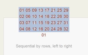
Figure 2 – “By rows, left to right” (the rack has eight vertical rows, starting with the row on the left)
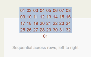
Figure 3 – “Across rows, left to right”
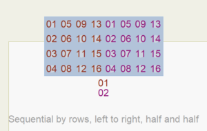
Figure 4 – “By rows, left to right, half and half” (requires two modules or slats because it includes two pin ranges)
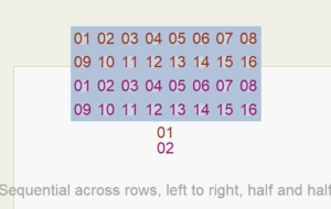
Figure 5 – “Across rows, left to right, half and half” (requires two modules or slats because it includes two pin ranges)
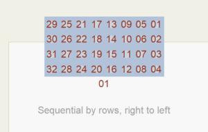
Figure 6 – “By rows, right to left” (pattern begins with the right-most vertical row)
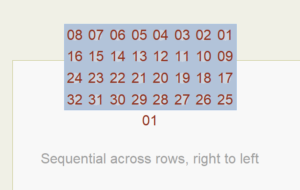
Figure 7 – “Across rows, right to left”
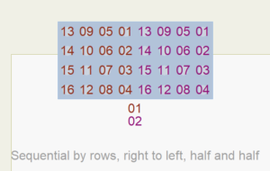
Figure 8 – “By rows, right to left, half and half” (requires two modules or slats because it includes two pin ranges)
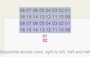
Figure 9 – “Across rows, right to left, half and half” (requires two modules or slats because it includes two pin ranges)
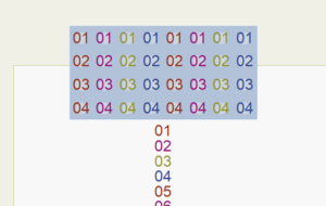
Figure 10 – “Sequential for each row” (requires eight modules or slats because it includes eight pin ranges, one for each row)