The idea of pre-wired pins is to pre-define the pin number order of the rack’s tube holders in a pattern that matches the firing system and makes it fast for the crew to set up. Look at the comparison in Figure 1. How much time would you save setting up the show if all your racks looked like the one on the right?
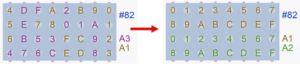
Figure 1 – Comparison of before/after using pre-wired pins. The rack has 32 tube holders; the modules have 16 pins.
For some racks like Evolved Pyrotechnics, Monetti iShot and PyroDigiT, pre-wired pins quite literally means the tube holders have built in physical wires that connect tube holders to a firing system slat. However, the idea of pre-wired pins applies to any rack, whether it actually has built in physical wires or not. If you define a rack in Finale 3D as having pre-wired pins, you can get a sequential pin number order of your choice, like the one on the right.
Angles
Pre-wired pins can be used for racks with fixed angle tube holders, or adjustable angle tube holders, or adjustable angle tube holders with angle range constraints. The addressing function needs to take into account the angles when assigning pin numbers.
Racks with fixed angle tube holders may leave gaps in the sequence of used pins of the module if there are gaps in the angles used in the fan. If a fan rack of 13 posts is pre-wired to pins 1-13 of a module, then a show that calls for a thinner fan of just 5 posts might use pins 1, 4, 7, 10, 13 of the rack. The pins in between may remain unused or may be used for other effects outside of the rack, like cakes.
Adjustable tube angle racks often have different angle ranges for the interior tube holders and the tube holders on the outside edges. The outside edge tube holders may rotate 90 degrees to fully horizontal, whereas the interior tube holders can only rotate about 50 degrees before they collide with the bases of their neighbors. Any effects at 90 degree angles can thus only be assigned to outside edge tube holders, which means they can only be assigned to the pin numbers of those outside edge tube holders.
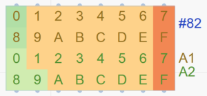
Figure 2 – For this rack with angle range constraints, only pin numbers 7 and F can be used for extreme angles to the right.
Spillage
The example rack of Figure 1 and Figure 2 has exactly twice as many tube holders (32) as the module has pins (16) so the modules’ pin numbers fit nicely in the rack. That’s not always the case. If the rack had 30 tube holders, then there would be 2 pins left over. If the rack had 25 tube holders, there would be 11 pins left over. Spillage is what you do with the leftover pins: do you use them for other effects like cakes or candles, or do you leave them fallow?
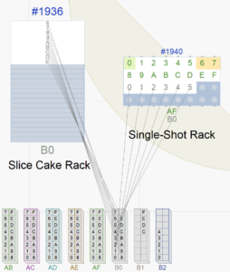
Figure 3 – The second module of single-shot rack #1940 spills pins 6 through E into the cake rack.
You could decide either way. If using the leftover pins allows you to reduce the number of required modules, then maybe that is a major factor in your decision. If the leftover pins don’t make a material difference in the number of modules or if you have modules to spare, then you may prioritize the efficiency of setting up the show over the savings of a module.
The example of Figure 3 shows leftover pins from single-shot rack #1940 (6 through E) being used for slice cakes in the cake rack #1936. These nine pins likely save a module for this position, but it does create the requirement that the module or slat serving the single-shot rack #1940 is close enough to the slice cake rack for the e-matches to reach.
How to setup pre-wired pins in Finale 3D
To use pre-wired pins, you need to setup two things:
- Configure rack definitions for pre-wired pins. If you are using racks from a supplier catalog, choose racks that are already configured for pre-wired pins in a way that matches your firing system module number of pins. If using your own rack definitions, select one of the “pre-wired pins” options in the definitions that matches your modules. For example, if a rack has 30 pins and your modules have 32 pins, you would choose a pre-wired pin pattern that runs from 1 to 30 (pins 31 and 32 unused). If your modules have 16 pins, then you would choose a half-and-half pattern that has two sequences of 1-15, one for each module (pin 16 unused).
- Choose the right addressing dialog options. In the addressing dialog or addressing blueprint choose the sorting criteria and constraints that fill the racks and handle leftover pin spillage the way you want. The choice of sorting criteria and constraints also depends on whether your racks have angle range constraints, and other factors. See the Table 1 below for guidance.
Configuring rack definitions for pre-wired pins
If you do “Racks > Create rack” or right click on a rack in your effects list or rack layout view, the dialog shown in Figure 4 presents two fields related to pre-wired pins.
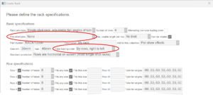
Figure 4 –Fields in the “Create rack” dialog related to pre-wired pins
The pre-wired pins field presents the options for the pin patterns. The choices for this field are shown in Figure 5.

Figure 5 –Pre-wired pins options
These options define sequential pin patterns 1, 2, 3, … that run along the rows or across them as in the Figure 6. The pin patterns are illustrated in Pre-wired pin options. The orientation of rows is explained in Rack “row” and standard orientation. A trick to interpret these options is: Hold your left arm out in front of you, wrist bent, fingers together pointing down. Your fingers are the rows, pinky finger being row #1. The option “By rows, left to right” thus starts with the first pin at the base of the pinky finger, progresses down to the finger tip, then continues at the base of the ring finger. If the rack is rotated 90° counter-clockwise to make the rows horizontal from the audience perspective, that’s like rotating your hand 90° counter-clockwise. In that orientation the first row represented by your pinky finger is closest to the ground, which is equivalent to closest to the audience in the rack layout view.
Choose the pin pattern that you like the most and that makes the most sense for your modules. If it takes two modules to cover all the tube holders, then choose one of the half-and-half options. If the modules have extra unused pins, such as two 16-pin modules covering a 25 or 30 tube holder rack, the extra pins can be used in other racks, which you can control with the addressing options. If the modules have fewer pins than the number of tube holders, such as an 18 pin module by itself on a 20 tube holder rack, the tube holders with out-of-range pin numbers will simply remain empty.
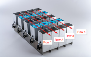
Figure 6 –Pin patterns traverse along or across the arrows; half-and-half starts over with pin 1 half way through the traversal.
After setting the pin pattern option, please set the pin loading order field (second red circle in Figure 4) to match it. Racks with multiple modules list the module numbers in the order that the pin sequences are encountered when traversing the tube holders by the loading order.
Choose the right addressing dialog options
Pre-wired pins require specific settings in the addressing dialog to make the addressing algorithm assign pins and racks optimally. There’s not just one definition of optimal that suits everyone, so there’s not just one configuration of settings that is right for everyone. Depending on whether your racks have adjustable tube holders on the ends of the rows that have different angle ranges from the interior tube holders, and depending on whether you want to allow leftover pins from one single-shot rack to be usable in other racks, there are a few configurations to choose from that work: Four.
The four configurations apply to the sort order, module constraints, pin constraints, and re-arrange checkbox of the addressing dialog, identified in Figure 7.
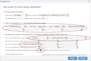
Figure 7 – The addressing dialog options relevant to pre-wired pins are: order, module constraints, pin constraints, and re-arrange.
The four configurations are listed in Table 1. As written, these configuration apply only to single-shot effects (all of them ending with “– Single-Shot” or “(If Single-Shot)” meaning they apply only to single-shots), which leaves the remaining empty fields available to you to add additional terms that apply to non-single-shot effects. For example, if you add “Rack Number” as a sort order option after the filled in fields of Table 1, the Rack Number term would apply to the order of the effects after the single-shot effects, and would also act as a tie breaker for any single-shot effects that have the same sort order priority based on the Table 1 filled in fields.
Table 1 – Addressing dialog option configurations
| Angle ranges | Leftover pins from rack’s modules | Addressing settings |
|---|---|---|
| All tubes have fixed angles or the same angle ranges | Usable in other non-single-shot racks |  |
| All tubes have fixed angles or the same angle ranges | Not used |  |
| Interior tubes -50..50; end tubes -90..50 and -50..90 | Usable in other non-single-shot racks |  |
| Interior tubes -50..50; end tubes -90..50 and -50..90 | Not used |  |
Regarding column 1 in Table 1, the only racks requiring special configuration terms are those for which adjustable tube holders at the ends of the rows have wider angle ranges than the interior tube holders that would run into their neighbors if tilted too extremely. The special configuration terms are required because the end tube holders are a limited resource. It is important to fill them with effects that require them. If the addressing algorithm wasted them on upright effects, then there may not be enough end tube holders to handle other effects at extreme angles.
Regarding column 2 in Table 1, none of the configurations permit pre-wired pins to be shared across multiple single-shot racks. Leftover pins from a single-shot rack are always either left unused or applied to individual cakes and candles (or sometimes shells) that are physically near the single-shot rack or that are reachable with scab wire. You can control what racks the leftover pins are shared with by adding “Rack Cluster” to the module constraints list and moving the racks close to each other in the rack layout view, or you can add “Custom Rack Field” to the module constraints list and fill in your own “virtual rack cluster” identifiers in the Custom Rack Field column of the racks.
The specific purposes of the sort order and constraint fields in the configurations are explained in Table 2 and Table 3.
Table 2 – Purpose of sort criteria terms
| Term | Explanation |
|---|---|
| Position Name | Almost all addressing configurations begin with Position Name to assign addresses one position after another. Nothing special about this term. |
| Tilt > 50° — Single-Shot | This term is required for racks that have interior tube holder angle ranges of -50..50° and ranges that exceed 50° for tube holders on the ends. Since the end tube holders are a limited resource it is essential to address the effects that can only go in end tube holders first, so they don’t fill up with other effects that don’t require them.
If your racks have interior tube angle ranges that are approximately 50° but not exactly, then pretend they have a 50° range and use the number 50 in the rack definition and the sort criteria. If the constraints are markedly different from 50° then use the actual angle in the rack definition and use “Most Horizontal Tilt — Single-Shot” in the sort criteria before the size constraint. The “Most Horizontal Tilt– Single-Shot” term will correctly allocate the end tube holders first, but it relegates the size constraint to being a tie breaker for same-angle effects instead of being a tie breaker for the group of effects > 50° and a tie breaker for the group of effects <= 50°. If positions contain multiple kinds of single-shot racks with different size range capacities, this sort configuration may use up holders in large effect size capacity racks on smaller angled effects that could have fit in small effect size capacity racks. |
| Size >= 50mm — Single-Shot | If positions include multiple kinds of single-shot racks, some capable of holding 50mm+ effects and others only holding smaller effects, then it is essential to address the 50mm+ effects first so the 50mm capable racks don’t fill up with smaller effects, leaving the 50mm+ effects nowhere to go. If your racks have a different size limit, use the 35mm, 40mm, 45mm, or 55mm version of this sort criterion, whichever is closest. There is no harm in including this term even if your positions don’t need it. |
| Most Horizontal Tilt — Single-Shot | Not as high a priority as the other sort terms, but “Most Horizontal Tilt — Single-Shot” prioritizes the angles first in a balanced way left/right. Including this term results in racks that have approximately even numbers of left and right effects, which makes the racks more symmetric and aesthetically pleasing. This term relies heavily on the “Rearrange effects to avoid collisions” function. |
Table 3 – Purpose of constraint terms
| Term | Explanation |
|---|---|
| Module restricted to Position | Module restrictions begin with Position unless modules are shared across positions, in which case all these Module constraints are usually on the Slat instead. |
| Module restricted to One Single-Shot Rack | This term restricts a module to at most one single-shot rack, but allows leftover pins from that rack to serve effects in other kinds of racks, like cakes, candles or even shells. |
| Module restricted to Rack (If Single-Shot) | This term restricts a module strictly to one rack if the module serves any single-shot effects. If any pins are left over, the pins will remain unused. |
| Pin restricted to Event (If Single-Shot) | This term restricts pins to a single event, but only for single-shots. This constraint is similar to the addressing dialog’s “Max e-matches per pin” (having the value 1), except that this constraint applies only to single-shots, leaving open the possibility of setting the max e-matches per pin to a larger number that would apply to other types of effects like shells. One way or another, restricting e-matches per pin to one for single-shots is required for pre-wired pins on single-shot racks. |