Fan row racks like the AVM SFX-20 racks, or the CraigCo MinCom racks, or the PyroDigiT PLS30E/45P+ racks can be configured in Finale 3D with pre-defined tube angles of your choice, or with adjustable tube angles that accommodate effects at any angle (see Fan row racks). In the real world, though, many fan angle racks have physical constraints that restrict the tubes to angle ranges. Sometimes the angle ranges are different depending on whether the tubes are on the ends of the rows or in the interiors, as shown in Figure 1. To accommodate these physical constraints, Finale 3D supports angle range specifications in the rack definitions like “-90..50” to indicate a range from minus 90 degrees to positive 50 degrees.
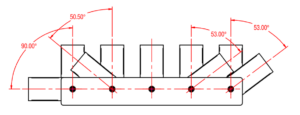
Figure 1 – Tubes on the row ends may be able to lean more than tubes in the middle of rows.
Tube angle range constraints are only supported for one rack structure, as chosen in the rack definition dialog: Single-shot rack, adjustable fan angles of tubes in each row; or more colloquially, “Fan row racks”. The tube angle range specifications go into the “Tube fan angles” fields for each row, as shown in Figure 2.
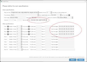
Figure 2 – Tube angle ranges are in the “Tube fan angle” fields for the rows — only for adjustable fan angles of tubes racks.
Figure 2 shows one possible definition for the CraigCo MinCom X5 20 Shot Rack, diagrammatically shown from the side in Figure 1 and also shown below in Figure 3. When defining fan row racks in Finale 3D, it is imperative that the rows in the “Create Rack” dialog are oriented to match the rows with fanned tubes in the physical rack. Looking carefully at the rack in Figure 3, you can see that the rotation rods with clamps go slight up and to the right in the image, perpendicular to the red arrows. The square holders rotate on the rotation rods. Thus from the physical construction, you can see that the rows of fanned tubes align with the red arrows, and contain five holders each. If you looked at this rack from the left side, it would match the diagram of Figure 1, which shows the angle ranges of the holders.
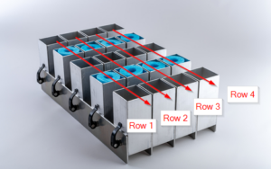
Figure 3 – The rows of a fan row rack definition in Finale 3D must match the fans of the rack in the real world.
In a show with fans spreading left/right from the audience point of view, the rack of Figure 3 would need to be rotated 90 degrees from its identity orientation to orient the fans left/right, which is typically how you would see it in the rack layout view in Finale 3D, sideways.
From Figure 1 and Figure 3, you can now make sense of the “Tube fan angles” fields of the associated rack definition of Figure 2. The tubes on the ends of the rows can aim outward horizontally at 90 degrees. The tubes in the interiors of the rows are restricted to 50 or 53 degrees, depending on the end tubes. Angle ranges in Finale 3D can’t have dependencies, so the conservative definition of allowable angles for these rows is: -90..50,-50..50,-50..50,-50..50,-50..90.
The first range in the list (-90..50) applies to the first tube in the row, which is the “top” tube in the rack’s identity orientation, and is the left-most tube if the rack is rotated 90 degrees counter-clockwise for left/right fans, as it typically is. Looking at Figure 1, the first range in the list represents the left most tube, and -90..50 represents the angle range from horizontal left to diagonal up-and-to-the-right.
Syntax for angles in the “Tube fan angles” field
The “Tube fan angles” field can be blank, meaning no restrictions, or it can contain a comma-separated list of specific angles or angle ranges. Angle ranges are in the syntax “X..Y” as in the previous examples. Specific angles are just numbers (“X”), and are equivalent to “X..X”. Since it is inconvenient to write -180..180 to mean no restriction for a particular tube, the syntax also supports leaving elements in the comma-separate list blank. A blank element is equivalent to -180..180. Thus “-180..180,-180..180,-180..180,-180..180,-180..180” has the same meaning as “,,,,”
Sorting by ‘Most Horizontal Tilt’ to assign tubes efficiently
Racks with angle ranges require some accommodations when addressing the show. When the tubes don’t all have the same angle ranges, which is usually the case if you are using angle ranges, then the addressing functions that assign tubes to effects can make bad decisions about which effects to put in which tubes.
The decisions won’t technically be wrong, because they will always satisfy the angle constraints you specify, but the decisions may not use the tubes that have the best fitting angle ranges for the effects assigned to them. A simple example is this: imagine a show that contains just eight effects, four aiming horizontally to the left and four aiming vertically straight up; the show will use one or more adjustable fan angle racks like that shown in Figure 3, with four fan rows. If the addressing function first assigns the straight up effects to the tubes on the left ends of the rows (the only tubes capable of aiming fully to the left), then none of the other tubes could accommodate the remaining four effects. The addressing function would need add extra racks to accommodate the remaining effects, even though a single rack could accommodate the eight effects if they were placed in the right tubes.
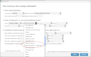
Figure 4 – The addressing sort criterion “Most Horizontal Tilt” fills rack rows from the outside-in.
The addressing sort criterion “Most Horizontal Tilt” shown in Figure 4 offers a solution for misallocating tubes at the ends of rack rows. Sorting the “Most Horizontal Tilt” first, the addressing function will seek first to find tubes for the effects with the most extreme angles, those fitting only in the end tubes. Returning to the example of eight effects with four aiming horizontally and four vertically, the horizontally aiming effects will be assigned first, while the tubes on the left ends of the rack rows are still available. The remaining four effects fill easily into any tubes. Thus the eight effects require only a single rack.
The “Most Horizontal Tilt” sorting criterion applies equivalently to left leaning and right leaning effects, causing the rack rows to fill from the ends toward the center if the end tubes are configured with the extreme angle ranges. For the common physical specifications of racks like the one shown in Figure 3, filling from the ends results in efficient use of the tubes.
Re-arranging effects to avoid collisions
The reason the end tubes get allocated for effects before the center tubes with “Most Horizontal Tilt” is that the end tubes are the only ones that can accommodate the extreme angles, so the extreme effects are forced into those tubes. But what about the less extreme angled effects? Using the tube angle ranges of Figure 2 as a specific example (the five tubes in each row having ranges -90..50, -50..50, -50..50, -50..50, -50..90), what about effects aiming between -50 and 50 degrees, which can be accommodated by the interior tubes?
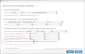
Figure 5 – The “Re-arrange effects…” option is a necessity with the “Most Horizontal Tilt” sort criterion.
The “Most Horizontal Tilt” sort criterion causes the more extremely angled effects to be assigned to tubes first, regardless of the direction they are aiming. Thus the order of assignment may intermingle left and right leaning effects. If the extremity of the effect angles isn’t forcing the effects into the end tubes, the effects may end up in interior tubes aiming toward each other on collision paths.
The “Re-arrange effects in adjustable angle racks to avoid collisions” option in the addressing dialog shown in Figure 5 fixes the colliding angles by re-arranging the tube assignments at the end of the addressing function after their initial assignments (see Re-arrange effects in adjustable angle racks to avoid collisions). This function is guaranteed to resolve all collisions as long as the most extreme angle ranges in the rack definitions are at the ends of the rows.
Using “fake” pre-wired pins to achieve a nice ordering of pins in the rack
You may not care about the pin order within the rack, but if you do care, the solution provided by “Most Horizontal Tilt” and “Re-arrange effects…” doesn’t achieve high marks by itself. Since the effects are assigned to tubes on the ends first, and then the tube assignments are rearranged, the end result is anything but a natural counting sequence of pin numbers along the rack rows. However, if that is what you want and if you use a single module per rack, then you can use the “Pre-wired pins” option for racks as described in Racks with pre-wired pins to achieve a good result.
The “Pre-wired pins” option was designed to support single-shot racks with pre-wired bases like the iShot racks by Monetti, but the option can also be used for non-pre-wired pin racks to guarantee a nice ordering of pins in the rack. The option simply adds constraints that the tubes in the rack match pin numbers in a pre-assigned sequence, left-to-right, top-to-bottom, etc., corresponding to the wiring of the rack or to an ordering you just happen to prefer. This option is possible only if you use a single module per rack. If you do use a single module per rack there’s no reason not to use this option. You get to specify a nice ordering of pins without any drawbacks.
