Large racks with multiple rows of tubes are easier to set up if there is some rhyme and reason to the arrangement of firing system pin numbers in the rack. For adjustable tube angle racks, the easiest way to guarantee a sensible layout of tubes is just to check the checkbox on the addressing dialog, “Re-arrange tubes of adjustable angle racks to avoid collisions,” which automatically provides an optimized layout with no tube angle collisions (see instructions here).
For non-adjustable angle racks or if you have a specific layout in mind, the tube loading order option in the rack definition enables you to define whether the pin numbers progress left-to-right-top-to-bottom, or in other arrangements. In combination with the addressing sort criteria that you specify when addressing the show, the tube loading order gives you a great degree of control over the pin arrangement.
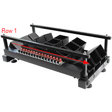
Figure 1 – Fan row rack with three rows of five tubes each.
The fan row rack of Figure 1 is an illustrative example. If you configure this rack as an adjustable fan row rack (see here), whose tube angles are defined according to the needs of the show, then the tube loading order will control whether the rack ends up with fan-like rows (as shown in Figure 1) or rows with mostly the same angle tubes (imagine if the first three tubes in Row 1 of Figure 1 aimed the same direction instead of the first tubes of the rows having the same direction).
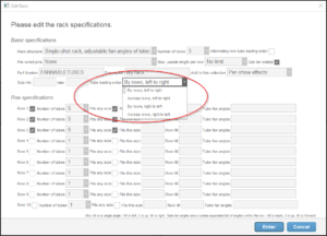
Figure 2 – Options for tube loading order
The tube loading order option is in the rack specification, as shown in Figure 2. Taking the 15-tube rack of Figure 1 as an example, the next set of figures illustrate the different tube loading order options for a show with 13 effects, leaving two tubes unused. Bear in mind as you look at these diagrams that the rows are defined in Figure 2 in the 5-tube direction, not crossways in the 3-tube direction. The definition matches the degrees of freedom of the tube angles in the real world. The Rack structure selector of Figure 2 is: “Single-shot rack, adjustable fan angles of tubes within each row”.
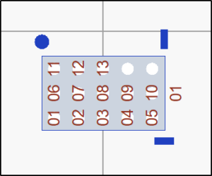
Figure 3 – By rows, left to right
The rack rows in the identity orientation are vertical in the top-down view, so the fan row racks are generally added to the show rotated 90 degrees counter-clockwise to make degrees of freedom of the tube angles tilt left/right instead of forward/back. The first rows in the identity orientation begins with the first tube in the upper left, counting down vertically. So if you rotate the rack counter-clockwise 90 degrees from the identity orientation, the first tube becomes the lower left, and the progress goes to the right, which is what you see in Figure 3.
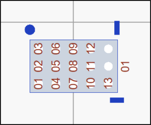
Figure 4 – Across rows, left to right
Figure 4 shows the “Across rows, left to right” loading order, which begins with the same tube but progresses to the right in the identity orientation, and equivalently progress upward across the 5-tube rows in top-down view when rotated counter-clockwise 90 degrees.
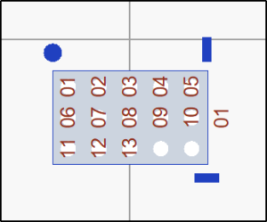
Figure 5 – By rows, right to left
If you want to begin in the upper left in the rotated orientation, then Figure 5 and Figure 6 are the right options..
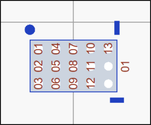
Figure 6 – Across rows, right to left
Referring back to the rack definition dialog in Figure 2, the “Alternating row tube loading order” checkbox in the upper right indicates each that alternating rows in the tube sequence will count in opposite directions, snaking the pin numbers back and forth (see here). If you think this back and forth option will give you cleaner wiring and you are otherwise ambivalent on the choice of “Across rows” or “By rows” loading orders, you should go with the “Across rows” options, at least for adjustable fan row racks.
Why? Because if your addressing sort criteria include “Angle” then the increasing pin numbers will represent increasing angles (toward the right). Thus the rows of Figure 6 and of Figure 7 would all be nicely fan-like. But if you checked “Alternating row tube loading order” for the “By rows” option of Figure 5, the second row would begin with pin 6 on the right, but pin 6 would be the most left-leaning effect in the row. Thus the second row would be almost certain to have colliding tubes that aim into each other!
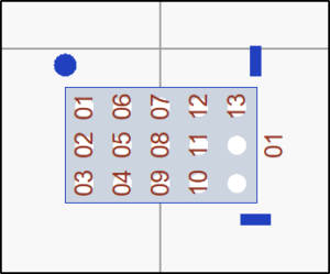
Figure 7 – Across rows, right to left, alternating row tube loading order
