Software Documentation

Software Documentation

RacksDocumentation

Intermediate Last updated: December 6, 2020

24 Fan row racks

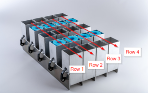
Racks like the Craig Co Racks and the PyroDigiT rack shown in Figure 1 have tube angles that are adjustable in one axis, in the plane of the row.  We call these fan row racks because the tubes in each row can be fanned out, as are a few of the rows shown in Figure 1.  The tubes can obviously also be straight up or all angled in the same direction, as are a few of the other rows shown in Figure 1.

The word “row” is a bit ambiguous, since you could consider either axis to be a row of tubes.  For purpose of these instructions, the “rows” are the lines of tubes that could be splayed out into fans or sheered.  In Figure 1, the rows are thus parallel to the red and black pin rails because that’s only axis with the degree of freedom in the hardware that allows tubes to be angled.   When you define racks in Finale 3D, row 1 of the rack is the left-most vertical line of tubes in the top-down view, as shown in Figure 4, below.  If you compare Figure 1 to Figure 4, you can see that the Finale 3D rack of Figure 4 would need to be rotated counter-clockwise in the top down view to match the picture of Figure 1 with the red lines matching up.

In Finale 3D there are two kinds of fan row racks — Pre-configured fan row racks, and Adjustable fan row racks.  In the real world, the two kinds of fan row racks are usually the same physical hardware.  The difference is in the design and planning phase.  Do you want to pre-define the angles of your rack tubes and design the show to fit in racks so configured, or do you want to let your show design dictate the angles of the tubes in your racks?

This article describes how to create both kinds of racks in Finale 3D, and how to address them so the angled tubes don’t end up aiming toward each other in the adjustable case.  The end of this article describes some of the pre-wired pin options that enable you to pre-define what firing system pin goes to each tube, which may be required by your hardware or may just be your preference for making rack setup more regular.


Figure 1 – Fan row racks like the PyroDigiT PLS30E/45P+ have rows of tubes that can be splayed out in the plane of the row.


Pre-configured fan row racks

The effects window contains various collections of effects like My Effects, Generic Effects, supplier catalogs, and possibly your company inventory in a single collection or spread out into multiple effects files (FDB files).   You choose between different collections with the blue selector in the upper right of the effects window.  The effects collections can contain racks, along with shells and other pyrotechnic devices.  Every item in the effects list has a unique part number, which is the reference used when the effect is inserted into the show or when the rack is inserted into the rack layout.

When you make a rack configuration of one of your racks to add to the show as a pre-configured rack, you need to add the new rack definition representing the pre-configured rack as as item in one of your effects collections.  That means you need to assign it a unique part number.  Let’s say you use racks like the one shown in Figure 1.  If you use 10 different configurations of this rack, then you would have 10 different items in your effects collection, representing the variations.  Each one would need its own part number, but they are related since they are all configurations of the same physical hardware, so you might make a part number scheme for your variations that has a common stem, like PLS30-A, PLS30-B, PLS30-C, for three different configurations, or maybe PLS30-FAN, PLS-30-STRAIGHT, PLS-30-ANGLES, if part numbers like that are more recognizable.

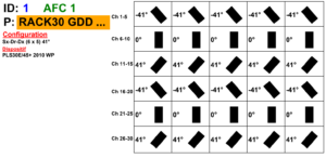
Figure 2 shows a possible configuration of the rack in Figure 1.  The actual configuration in Figure 1 is somewhat different, but the physical hardware is compatible.  Let’s use Figure 2 as the basis for an example of defining a rack with pre-configured fan angles.


Figure 2 – A diagram showing six rows with the tube angles and pin ranges for each row.


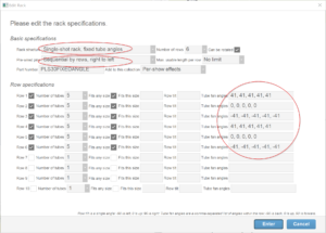
The corresponding rack configuration in Finale 3D is shown in Figure 3.  You can invoke this dialog with the command “Racks > Create rack…”.  The salient input fields are circled in red.  The first indicated field defines the rack structure — “Single-shot rack, fixed tube angles”.  The reason this is the correct selection, rather than any of the adjustable tube options, is that we are “pre-configuring” the rack.  From the perspective of Finale 3D, none of the angles are adjustable!

Figure 3 – Rack definition in Finale 3D corresponding to the specifications in Figure 2.


The diagram of Figure 2 also specifies the pin numbers (“Ch” in the diagram) for all the tubes, as is common for PyroDigiT racks with built in firing system rails.  You will need to specify the pre-wired pin order in the second red circle of Figure 3 in your rack definition.  The pre-wired pins option applies equally to pre-configured fan row racks and adjustable fan row racks, so we will return to this subject after describing the basics of adjustable fan row racks.


Adjustable fan row racks

Adjustable fan row racks are usually the same hardware as pre-configured fan row racks, so Figure 1 could just as easily represent an adjustable fan row rack.  In Finale 3D, you define an adjustable fan row rack by setting the rack structure selector in the first red circle of Figure 3 to, “Single-shot rack, adjustable fan angle tubes in each row”.  Having declared that the tubes are adjustable, you obviously shouldn’t specify the tube angles within the rows, so the circled area on the right side of Figure 3 should be blank.

The addressing operations in Finale 3D that assign firing system modules and pins to the effects also assign the racks and tubes to the effects.  The tube angles of adjustable fan row racks are undefined until effects are assigned to them, at which point the tube angles take on the angles of their effects.  In this manner it can be said that the addressing operations of Finale 3D choose the tube angles of the adjustable fan row racks.

You might care about how those angles are chosen.  The obvious example that you definitely care about is tube angles aiming toward each other, which would potentially send effects on a collision course (if the configuration is even possible in the real world).  On their own, the addressing operations have no inherent collision avoidance rules.  The addressing operations simply assign the next effect, according to the sort order you specify, to the next available tube that is compatible, according to the order of the racks you can specify and the tube loading order of the rack’s definition.

By default, the tube loading order for all racks begins with the first tube of the first row, progresses through all the tubes of the first row, then onto the next row, and so on.  Thus in Figure 4, below, the top left tube is the first, the tube to its right is the sixth, and so on.  Imagine that rack rotated 90 degrees counter clockwise, which enables the angles of the tubes in each row to fan out or aim left and right.  This is the orientation of this kind of rack with angles resulting from the function “Racks > Add racks for show” because the original orientation shown in Figure 4 could not accommodate left or right angles, given the degrees of freedom of the tubes in the rack definition.

In the rotated orientation, the first tube of the first row is actually in the bottom left, as shown in Figure 5.  Thus the bottom left tube will be the first available tube for the addressing function to use for the first effect it assigns according to the sort order you specify.   It is essential for this kind of rack that your addressing sort order sorts by “Angle” to ensure this left-most tube in the rack is aiming to the left at least as much as its neighbors to the right of it.  Progressing with the tube assignments in the bottom row toward the right, the effect angles and thus the tube angles will only hold or tilt more to the right.   The tube angle sequence will continue to progress through the remainder of the rows.  Within every row the progression of tubes will continue to hold or tilt more to the right.  Thus, if you include “Angle” high enough in your addressing sort criteria, such as sorting by “Position > Angle”, you will avoid all tube angle collisions in adjustable fan angle racks.


Tube loading order options

The default tube loading order for a rack is “By rows, left to right” which refers to the identity orientation shown in Figure 4.  In that diagram, the upper-left tube is the first, then progressing down the first row for the second, third, fourth and fifth tube, then the sixth tube beginning at the top of row 2, etc.  When the rack is rotated 90 degrees counter-clockwise as in Figure 5, the first tube is the bottom-left, and the next tubes progress to the right and then continue in the next row above, working their way to the last tube in the top right of the diagram.

If you are using adjustable fan row racks you may prefer each row (horizontally drawn in Figure 5) to be fanned out with left leaning tubes on the left side of the row and right leaning tubes on the right, as opposed to the first row having the left-most effects and the last row having the right-most effects.  Both options have no tube collisions, so it is a matter of preference.  Do you prefer the rows each looking like a fan, or do you prefer that tubes in a row have the same angle, to the extent possible?

You can achieve “each row looks like a fan” result by including “Angle” sufficiently high in your addressing sort criteria and changing the tube loading order or your rack definition to “Across rows, left to right” or “Across rows, right to left”, which refer again to the identity orientation shown in Figure 4.   “Across rows, left to right” progresses along the top of the diagram beginning in the upper left, which means beginning in the bottom left and progressing upward in Figure 5.  As long as your effects are sorted by “Angle” this tube loading will put the left most leaning effects on the left sides of the horizontal rows of Figure 5, resulting each each horizontal row being fan-like instead of each row having mostly a single angle.  The “Across rows, right to left” option also produces fan-like rows, except starting with the first pin in the upper left of Figure 5 instead of the bottom-left.

The tube loading order options also apply to the pre-configured fan row racks, except they generally aren’t as important for pre-configured fan row racks since tube collisions aren’t a factor and since the pre-defined angles will likely force the pin order to jump around to find compatible tube angles.


Pre-wired pins options

Similar to the tube loading order options, the pre-wired pins options pertain to the order of the tubes in the rack, except that the pre-wired pins options force the tubes to have specific pin numbers, enabling you to use racks with pre-wired conduits or single-shot bases like i-shot or Evolved.

In Finale 3D the “rows” that the rack configuration in Figure 3 defines are vertical if you are looking at the rack in a top-down view as in the rack diagrams.  The reason for this is that a simple wooden rack with one “row” is naturally oriented vertically in the top-down view, so if a rack definition had multiple rows, the additional rows would also be vertically oriented, stacking to right like a picket fence in the top-down view.  Thus in the identity orientation the first row is the left-most vertical row of tubes; the second row is one over to the right, and so on.


Figure 4 – “Rows” in Finale 3D rack definitions are vertical rows of tubes, starting on the left.


The rows in the specifications in Figure 2 are horizontal, so to match it with the rack defined in Finale 3D you need to rotate the Finale 3D rack 90 degrees counter-clockwise in the rack layout.  If you use the “Racks > Add racks for show” function, Finale 3D will automatically insert the rack in the correctly rotated orientation to accommodate the shot angles in the  show.  After rotating the Finale 3D rack 90 degrees counter-clockwise, it looks as shown in Figure 5.


Figure 5 – After rotating a Finale 3D rack 90 degrees counter-clockwise, the first row is on the bottom.


Comparing Figure 5 to Figure 2, you can see that row 1 of the Finale 3D rack definition corresponds to the bottom row of the specifications shown in Figure 2.


Figure 6 – The pre-configured rack after addressing has pin numbers corresponding to the specifications of Figure 2.


It is important to note that pin assignments to the rack are 100% independent of the addressing order of assignment.  Based on the pre-wired pin option of Figure 3, pin 2 can only go in one place — the tube near the top left corner of Figure 6.  The tube angles of Figure 3 specify that that tube has a pre-configured angle of -41 degrees.  You might wonder, “What would happen if pin 2 were assigned to an effect at a different angle, not -41 degrees?”  The answer is, that can’t happen!  The “Addressing > Address show…” function takes into consideration rack constraints when it assigns the pin addresses to the effects.  It would never assign pin 2 to an effect with any other angle than -41 degrees if the available racks in the effect’s position were configured as in this example.

The pre-wired pins options discussed are just a few of the available options.  If your 30 tube rack used two modules with 15 pins each instead of a single module with 30 pins, then you might use the “Sequential by rows, right to left, half and half” option to create two pin ranges of 1-15 along the rows instead of a single pin range of 1-30.  If you wanted pin sorting different from the specifications in Figure 2, you might choose to use the “left to right” options for pins, or maybe rotate the racks 90 degrees clockwise instead of counter-clockwise.  It’s up to you.  Using the various options, you can define racks to match the suitable configurations for your racks, your firing system, and whatever wiring conventions you want to use.


Limitations of adjustable fan row racks with pre-wired pins options

Using the tube loading order options you can control whether adjustable fan row racks have rows that look like fans, or rows with mostly the same angle tubes.  You may want the same control while also employing a specific pre-wired pins option.  Is that possible?

Unfortunately, it is not.

The pre-wired pins option itself will define whether you end up with rows that look like fans or rows with mostly the same angle tubes, and there’s nothing you can do about it if your hardware dictates what pre-wired pins option to use.  The “Across rows” pre-wired pins options yield fan-like rows.  The “By rows” pre-wired pins options yield rows with mostly the same angles.

To see why, look at Figure 6, which could represent a “By rows” pre-wired pins option since the number sequences go along the rows instead of across the rows.  Imagine that all the angles were sorted left to right in keeping with the pin numbers, pin 1 being the most left-leaning and pin 30 being the most right leaning.  You can see that the rows (horizontal in the figure) would thus have mostly the same angles and would not be fan-like.  Now imagine the pre-wired pins option was an “Across rows” option that progressed down from the top-left instead of to the right.  Bearing in mind that the rows are horizontal in the figure, this pre-wired pins option would result in fan-like rows.  Thus if your rack hardware dictates the pre-wired pins option, then you’ll get whatever pattern follows.