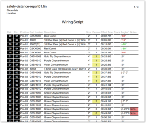
The Wiring Script report contains the information to wire up the effects in the show. Sorted by rail and pin, the rows in the script provide the position, effect part number and name, size, number of devices, angle, and notes. Notably, the report also has conditional formatting to group together rows that are on the same firing pin, and to highlight pins with multiple e-matches, angled effects, or notes.
Since every pyro display company has its own style, you may want to customize this report to add or remove fields or to change the formatting. The default report works for most purposes, and is also a good basis to work from if you make your own report.

Figure 1 – The Wiring Script report contains the information to wire up the effects — and some fancy formatting.
The first two columns are inverted colors just to emphasize them and to make this report recognizable. The horizontal lines group the rows by rail and pin. If multiple shells of the same effect type are fired together from the same rail and pin, then they will appear as a single row in the script with the Devices column counting the number of shells; but if the shells are of different effect types, then they are split out across multiple rows, one for each type of effect.
From the Script window’s blue gear menu, do “Edit report template…” and choose “basic_wiring_script_portrait” to see the report configuration dialog. Paragraph 2 of the dialog controls what script rows are combined together versus listed separately in the report. As shown in Figure 2, script rows are combined only if they have the same Rail, Pin, Position, and Part Number; or if they are chains.

Figure 2 – Script rows are combined only if they have the same Rail, Pin, Position, and Part Number; or if they are chains.
In the example in Figure 1, the group of three rows on 01/01 represent three shells; the group of three rows on 01/03 represent four shells; the single row for 02/03 represents two shells; and the single row 02/04 represents six shells. The yellow highlights call out any row whose pin has multiple e-matches attached to it. The yellow sections in the Figure 1 illustrate the e-match counting logic. It is easy to see why the yellow cells are yellow, but what about the “3” cell just above the yellow “6” cell at the bottom of the page? Why isn’t it yellow?
The red notes fields offer a hint. The effects on rail, pin 02/05 and /02/06 are in chains of three shells. Thus the 02/05 row only requires a single e-match for the chain and is therefore NOT yellow; whereas the 02/06 row has two chains of three shells and therefore requires two e-matches, turning it yellow.

Figure 3 – The conditional formatting parameters highlight fields based on logical expressions.
Conditional formatting
From the Script window’s blue gear menu, do “Edit report template…” and choose “basic_wiring_script_portrait”, to see the configuration dialog with the paragraph 6 shown in Figure 3. For this report,
- Option A and G invert the colors of the Rail and Pin columns.
- Option C groups the rows with the same rail and pin, putting lines between the groups.
- Option D and E add the colors for angled effects.
- Option F highlights in yellow the rows whose pins have multiple e-matches. The full expression in the box is, “[or [= fullAddress prev.fullAddress] [= fullAddress next.fullAddress] [and [not chainRef] [> numDevices 1]]]”. Options D-H are programming language expressions. If you are not a programmer, you can copy/paste examples from existing report templates.
- Option H highlights the notes in red if they are not blank.
