The paradigm for assigning firing system addresses and racks in Finale 3D is to choose the firing system; then choose an “assignment order” for the effects by specifying a set of sort criteria, like “Position > Size > Angle”; and then, optionally, choose “addressing constraints” that prevent modules from serving effects across multiple positions or clusters of racks or the like. The three choices — firing system, assignment order, and constraints — are the three paragraphs of the addressing dialog from the command “Addressing > Address show…” and similar addressing functions, as shown in Figure 1.
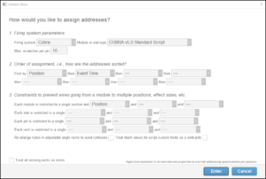
Figure 1 – The addressing choices: firing system, assignment order, and constraints.
These three addressing choices are natural if you want to sort your modules by size, or angle, or such, but what if you want to sort your modules according to how you’ve arranged your racks, left to right, which may not be strictly by size first, or by angle, or by any consistent sorting criteria whatsoever? What if you wanted your modules sorted smoothly left to right in the rack layout shown in Figure 2?
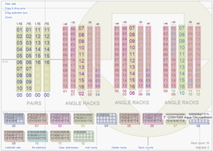
Figure 2 – How can you make the module numbers go from left to right (00 to 12) when sorting by angle or size doesn’t work?
Notice in the rack layout of Figure 2 that the module numbers just below the racks go from 00 to 12, left to right. That’s a hint that this module sorting is possible, but a closer inspection of Figure 2 shows why it may be difficult. The yellow racks are 3″ racks, and the red racks are 2″ racks. They are intermixed, left to right, so the modules clearly aren’t sorted by size. If you look at the angles above the racks, you can see that the angles also are intermixed, so sorting by angles wouldn’t produce these module addresses either.
The show designer of this show had something specific in mind for this rack arrangement. The four yellow racks on the left are pairs of 3″ effects that fire together in V’s. The show designer has laid out those racks in left/right pairs so the e-match wires are close together. The top pin numbers of the left-most two racks are both 01; the next tubes down are 02, etc.
The three other groups of racks, each with a yellow 3″ rack flanked by four 2″ angled racks, correspond to the physical rack structures the designer uses — assemblies of five racks fanned out at pre-defined angles with the center rack upright and the outer racks tilted at 30 and 45 degrees.
The designer thus doesn’t have much choice for how to arrange the racks. His goal is to assign firing system addresses optimally for the rack layout that he inherits.
Sorting by “Rack Number”
Every rack in the layout has a unique “Rack Number” that you can edit in the table in the Racks window, as shown in Figure 3. You can also select the racks and then right-click on them to do “Renumber racks left to right” from the context menu, or you can do “Racks > Renumber all racks consecutively” from the main menu to eliminate the gaps in the number sequence. See Renumber racks for examples and more information about renumbering.
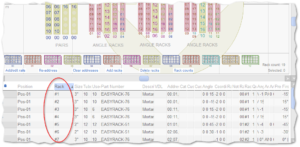
Figure 3 – You can edit rack numbers directly in the table or select and right-click groups of racks to renumber them left to right.
Once you’ve renumbered the racks in the order you want for the addresses, add the term “Rack Number” to the sort criteria of paragraph 2 in the addressing dialog, as shown in Figure 4. Figure 4 produces the addressing result shown in the original example, above, in Figure 2.
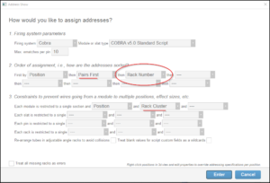
Figure 4 – Sort by “Rack Number” to assign addresses based on layout of racks.
Other fine-tuning optimizations
The addressing dialog of Figure 4 adds another sorting term to sort the pairs first, and adds a constraint to restrict modules to not be shared across clusters of racks. These fine-tuning optimizations for addressing are highlighted in Figure 5. Sorting by Rack Number doesn’t require these other optimizations. The example just aims to illustrate a realistic scenario that entails some additional considerations.
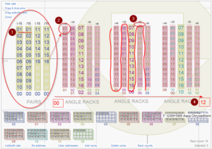
Figure 5 – (1) Pairs first; (2) Rack Cluster constraint; (3) Reverse loading order; (4) Sorting by Rack Number.
The “Pairs First” sorting term in paragraph 2 of the addressing dialog guarantees that the pairs of effects are addressed first, ensuring that the pairs line up evenly in the racks, as you can see near the #1. If the show had other individual shells at those angles, addressed prior to the pairs, then the pin numbers of the pairs might not line up.
The Rack Cluster constraint prevents the module serving the pair racks from continuing on with e-matches to the 2″ racks near the #2 in Figure 5.
A close look at the pin numbers in the non-pair clusters of racks shows that the pin numbers wrap around, zigzagging as drawn next to the #3 in the figure. Not everybody wants pin numbers laid out that way, but if you do, then right click on the racks that you want to load in the reverse order and select “Reverse tube loading order.” The small horizontal just bar above two of the racks in each of those clusters is an indication that their loading order is reversed.
Finally, the #4 calls your attention to the module numbers, sorted left to right in the diagram to match the rack numbers.
